Let's get started!
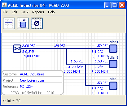
Fig. 1
Using PCAD is quite simple. You add equipments as per your design, you connect these equipements to the GAS supply with lines, you edit the values to match your requirements, and you're done!
PCAD will display the diameter, pressure and flow for each section. It will also generate a lot of reports and a bill of material.
Note: if you are not familiar with graphic programs read the How to draw section. Learning how to use the powerful PCAD GUI (graphic user interface) takes only a few minutes!
We will start with our ACME Industries New boiler room project. See figure 1.
Let's add the equipments
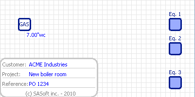
Fig. 2
Click on the Equipment button and move the mouse to the position where you want this equipment to be located. When there, just click: the equipment will be locked to the grid.
When you release the button, there is still an equipment layout attached to the pointer. This means you are still in the add equipment mode. Move the mouse to the position where you want the 2nd equipment to be located and click: this equipment is now locked to the grid. And so on for equipment no 3.
When you're finished your drawing should look like figure 2.
Let's connect these equipments
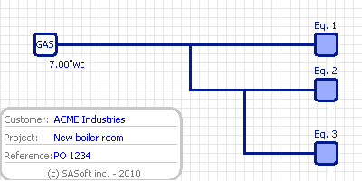
Fig. 3
We have to supply gas to these boilers. The way to do it is to connect each boiler to the GAS supply with lines.
Click on the Line button and start drawing the lines so each boiler is connected to the GAS supply. The way the lines connect to the boilers, to the other lines and to the GAS supply must respect your piping layout.
When you're finished your drawing should look like the figure 3.
Size these pipes!
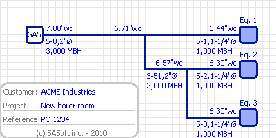
Fig. 4
Click on the Diameter button. PCAD makes the calculations based on its default values (gas pressure: 7 in. w.g.; pressure drop: 1 in. w.g.; sections lenght: 10 ft, no fittings; equipments: 1000 MBH input). The diameters, pressures and flows are now displayed.
If you made no mistakes at connecting the equipments to the GAS supply, PCAD shoul look like figure 4. Otherwise an error message was displayed, with error explanation and suggested correction. In this case you have to make the corrections then click the Diameter button again.
So far so good. But our project data are different from the PCAD default values. These data are:
- Supply pressure: 2 PSI; design pressure drop: 1 PSI;
- Boilers input: no 1: 6 000 MBH; no 2 and 3: 4 000 MBH ea.
- Piping sections: lenght: 50 ft; 90 elbows: 5; for simplicity stake all the sections have the same lenght and the same number of fittings.
We have to make some adjustents.
Change the supply pressure
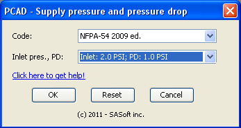
Fig. 5
To change the GAS supply pressure, move the mouse over the GAS supply (you will know you're over it when it turns blue). Right-click and select Edit in the popup menu. The Supply pressure and pressure drop dialog box, shown in figure 5, will be displayed.
Select the applicable Code, select the inlet pressure and pressure drop and then click OK.

Fig 6
PCAD will compute the project data according to the new pressre and pressure drop. This action will give you the opportunity to see a PCAD safety feature. Because the defaut supply pressure is 7 in. wg., the default operating pressures (min and max) for the equipmentts are set accordingly. Because the supply pressure is now 2 PSI, the pressure at the boilers is now over their maximum operating pressure. PCAD will generate a warning message. You can see this message for boiler no 1 in figure 6.
Change the boilers operating pressure and flow
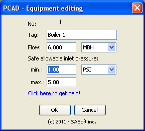
Fig. 7
To change boiler no 1 operating pressure bring the mouse over it (it will turn blue, as you already know!). Right-click to display the popup menu and select Edit. The equipment editing dialog box will be displayed. See figure 7.
Edit the values as you need. You have to make sure the min. and max. inlet pressure are safe for the supply pressure you have selected. This will avoid pressure compliance error messages.
When you're done click OK. PCAD will compute the diameters, pressures and flows and will display them.
Enter lenght and fittings for each section
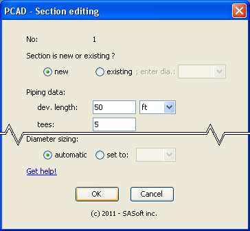
Fig. 8
Move your mouse over section S-1, the section attached to the Boiler no 1 (it will change color when you will be over it). Right-click to display the popup menu and select Edit. The section editing dialog box will be displayed. See figure 8.
Let's say the section developped lenght is 50 ft, so enter 50 in the dev. lenght field. And also let's say there are 5 90 elbows in this section so enter 5 in the 90 elb field. Then click OK. PCAD will compute diameter, pressure and flow, and display the calculations result.
We now have to enter lenghts and fittings for every other section. In this example, we assume all sections have the same developped lenght(50 ft) and the same no of 90 elbows(5). We can go over each section, display the Section editing dialog box and enter all the data. But in this project all sections have the same data. So go over section S-1, righ-click to display the popup menu and select Copy. All the data of this section will be copied.
Now move over section S-0, the section attached to the GAS supply, and right-click. In the popup menu select Paste data from S-0. And repeat the process for S-2, S-3 and S-51. You're done! PCAD should now look like figure 1.
Back to top