Gas supply
Fig. 1
The GAS supply is the rounded-corner square with a dark blue outline and the word "GAS" written inside, as can be seen in figure 1.
It represents the utility meter, a pressure regulator or anything else that supplies gas to your distribution piping.
Editing the supply pressure and the pressure drop
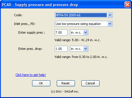
Fig. 2
PCAD default supply pressure is 7.0 in. w.c., and the default design pressure drop is 1.0 in. w.c.
To change the supply pressure and the design presure drop, mouve the mouse over the GAS supply and right-click to display a popup menu. Click edit to display the Supply pressure and pressure drop dialog box. See figure 2.
First select the Code that applies to your project. You have 2 options: NFPA-54 or CSA B.149.1
Then, in the "Inlet pres., PD:" dropbox select the design criteria you want to use for your project. You have 3 types of choices:
- Pre defined combinatiions of supply pressure and pressure drop; these combinations match the sizing tables of the Codes;
- Use low pressure sizing equation
- Use high pessure sizing equation
Some predefined combinations, such as NFPA-54 2nd combination Inlet: < 2 PSI ; PD: 0.5 in. w.c., call for a range of supply pressure. If you select this combination, you will have to enter the supply pressure you want to use.
If the predefined combinations don't suit your needs, use either the low pressure or the high pressure sizing equation. You will have to enter the supply pressure and the design pressure drop, as can be seen in Fig. 2.
Note: it may be useful to know that Codes tables are computed by using either the low or high pressure equation. This means that if you use the predefined combination "Inlet: 3.0 PSI; PD: 2.0 PSI" you will get the same result as if you use the high pressure equation, set the supply pressure to 3.0 PSI, and the pressure drop to 2.0 PSI.
The unit you choose for the supply pressure will be used to display the pressure at any point on your piping - except at equipment inlet with a different pressure unit.
Error checking
When your selection requires that you select the supply pressure (maybe the pressure drop too) PCAD displays the valid range. If the value you entered is outside of the valid range, the value and the valid range will be displayed in red, as a warning. Make sure your value is within the specified valid range.
This warning may be triggered when you change the unit. Just set the value within the valid range.
Closing the dialog box
When you have made your decision click the OK button to save the changes, close the dialog box and get back to PCAD.
Click the Cancel button to close the dialog box and return to PCAD. The supply pressure and the design pressure drop will remain unchanged.
Click the Reset button to display the default values.
NFPA-54
Table 6.2(c)
Table 6.2(c) displays gas flow for a 2.0 PSI inlet pressure, and 1.0 PSI pressure drop. This table has been computed with the low pressure equation, even if the low pressure equation is to be used for pressures 1.5 PSI or less. You will not be able to replicate that table with PCAD because the low pressure equation requires an inlet pressure of 1.49 PSI or less and a pressure drop of 2 in.wg. max.
Table 6.2(e)
We did not make Table 6.2(e) available in the Inlet pressure and pressure drop combo box (6.2(e): pressure : 5.0 PSI; pressure drop: 3.5 PSI). The reason is that computations with the high pressure equation do not match the flows of this table. The best match for this table is to use the high pressure equation, set the supply pressure to 5 PSI and the pressure drop to 3.25 PSI.
CSA B.149 and the F factor
The F factor
CSA B.149 uses the F factor, a fitting allowance factor, in the piping sizing equations. F = 1.2 for tables A.1 to A.4 (supply pressure: 2 PSI or lower), and F = 1.0 for tables A.5 to A.7 (supply pressure: 5 PSI or higher). This means that for tables A.1 to A.4, the lenght used in the equation to compute the pressure drop is equal to the lenght to the left of the table, multiplied by 1.2.
For tables A.1 to A.7 PCAD uses the same F factor as CSA B.149. For low pressure and high pressure equations, PCAD uses F = 1.0.
For example, the Table A.2 (7-14 in.wg supply; 1 in.wg drop) shows that a 1-1/4 pipe 50 ft long can carry 768 MBH to have 1 in.wg pressure drop. If you use PCAD with the same table A.2 and 50 ft pipe length, the flow to have 1.0 in.wg pressure drop in a 1-1/4 pipe is 767 MBH. In PCAD now replace the table A.2 by the low pressure equation (set to 7.0 in.wg supply and 1.0 in.wg pressure drop): at 767 MBH the pipe length, to have 1.0 in.wg drop in a 1-1/4 pipe, is 60 ft (= 50 ft x 1.2). (Don't worry about the 1 MBH difference: it is caused by rounding the calculations.)
Back to top