How to draw
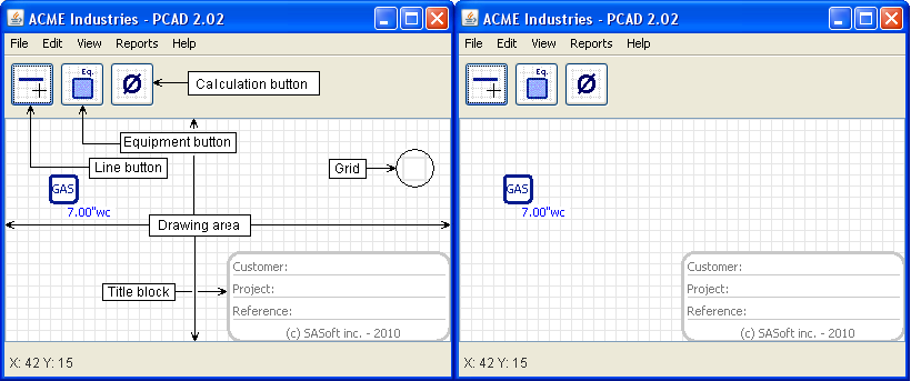
Fig. 1 - Move the mouse over to remove the description
This section shows you how to build your piping system model, by adding equipments and lines to the drawing.
The GUI
PCAD ease of use comes from its graphic user interface (GUI): it allows you to easily make a clear layout of your design. So let's start by descibing it. See figure 1.
- When PCAD is launched, the screen looks like the picture on the right (except for the elements description)
- Drawing area: this is the part of the PCAD window where you add lines and equipements to build your layout
- Line button: you click it to start drawing lines
- Equipment button: you click it to add equipments
- Calculation button: you click it to have PCAD compute pipes diameter, pressure, etc.
- Grid: lines endpoints and equipements snap to the grid; it can be turned on or off as you wish, from the View menu (lines and equipments snap to the grid even if it is not visible)
- Title block: can be located anywhere on the drawing; right click to edit its content; the title block can be hidden or set visible from the View menu
- The PCAD window can be resized as per your needs
Adding equipments
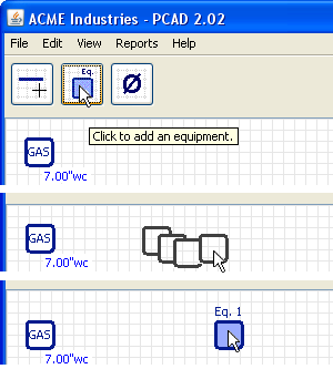
Fig. 2
To add an equipment (see figure 2):
- Click on the Equipment button
- Move the mouse over the drawing area up to where you want the equipment to be located; while you move the mouse you will see the outline attached to the end of the pointer
- Click again: the equipment will be locked at that location
When you release the mouse button, you see the equipment outline again. If you want to add another equipment, move the mouse to the location where you want that next equipment to be located, and click. If you don't want to add another equipment, just right-click.
To move an equipment:
- Bring the mouse over this equipment (you will know you are over it when it turns to dark blue)
- Press the left button - the pointer will turn to the 4 arrows style
- Hold the left button down and drag the equipment to its new location
- Release the button: the equipment will be locked at that new location
Equipments can be edited, copied or deleted. Information from another equipment can also be pasted to an equipment.See the Equipments section for more information.
Adding lines
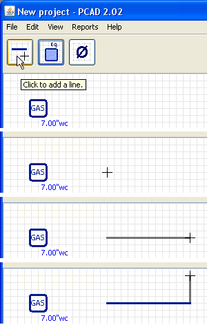
Fig. 3
To add a line (see figure 3):
- Click on the line button
- Move the mouse over the drawing area: the pointer will change to a crosshair
- Move the mouse to the location where you want the 1st point of the line and click
- Move the mouse to the 2nd point of the line and click. Your line is drawn
When you release the button the grey line will be displayed again and will follow the mouse. If you want to add another line just move the mouse to the 2nd point of this new line and click. If you don't want to add another line just right-click.
To move a line :
- Bring the mouse over the line to move (you will know you are over it when it becomes highlighted)
- Press the left button - the pointer will change to the 4 arrows style
- Hold the left button down and drag the line to its new location
- Release the button: the line will be locked at that new location
To stretch a line :
- Bring the mouse over the end of the line to stretch (you will know you are over it when it becomes highlighted)
- Press the left button - the pointer will change to the 2 arrows style
- Hold the left button down and drag the endpoint as required
- Release the button: the point of the line will be locked at that new location
To delete a line:
- Bring the mouse over the line you want to delete (you will know you are over it when it becomes highlighted)
- Press the right button - a popup menu will be displayed
- In the popup menu click on Delete
- A dialog box will ask you to confirm
- Click Yes to delete the line, No to cancel
Some rules apply
Equipments:
- At least 1 equipment is required per project. So you cannot delete an equipment if it is the last one remaining.
- An equipment must not overlap another equipment
- An equipment must not overlap the GAS supply
Lines (see figure 4):
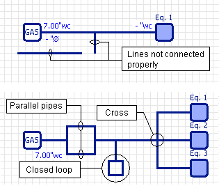
Fig. 4 - Don't do that!
- The GAS supply must be connected to one and only one line
- An equipment must be connected to one and only one line
- Any line must be connected to the GAS supply, to an equipment or to another line
- Line with 1 or 2 unconnected ends are not allowed
- Crosses are not allowed - only tees
- Closed loops are not allowed
- Parallel pipes are not allowed
When you click the Calculation button, PCAD first performs a check of your drawing. If anyone of the above rules is not respected, PCAD will display a dialog box telling you what is the error and suggesting how to correct it. Make the required correction and click the Diameter button again
Back to top