Sections
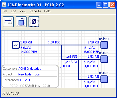
Fig. 1
A section is a set of 1 or more lines connecting:
- the GAS supply to an equipment
- the GAS supply to a tee
- a tee to an equipment
- a tee to another tee
As can be seen in figure 1, section S-0, S-1, S-2, S-3 and S-51 have 1 or more lines, and connect the GAS supply to a tee (S-0), a tee to an equipment (S-1, S-2 and S-3), and a tee to a tee (S-51)
Sections are created when you click the Diameter button. The sections are created from the lines you have drawn.
Editing a section
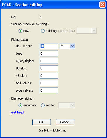
Fig. 2
The section properties are
- new or existing
- developped length
- no of tees
- no of weldolets and threadolets
- no of 90 deg. elbows
- no of 45 deg. elbows
- no of ball valves
- no of plug valves
- sizing auto or set manually
Thes properties can be accessed through the Section editing dialog box, shown in Fig. 2. To display it, move the mouse over a line of that section and right-click. In the displayed popup menu click on Edit.
New and existing sections
If your project includes a tap to an existing section, you will have to check the pressure drop in that section too. So you will include that section in your PCAD design.
As this section is existing, you have to let PCAD know its diameter by selecting it in the dropbox. PCAD will compute the pressure drop in that section according to its properties and flow.
Sections set as existing have an (E) attached to their section diameter. For example, if section S-67 is existing and has a diameter of 2" PCAD will display its diameter as 2"Ø(E). The section linetype will be dash.
Existing sections will not be included in the bill of material.
Note: when 1 or more sections are set as existing the pressure drop and equivalent lenght of these sections are substracted from the calculations. So let's say we have set the system pressure drop to 1 in.wg, with a total equivalent length of 200 ft, including an existing section with a pressure drop of 0.2 in.wg and an equivalent lenght of 40 ft. The new lines are sized for a pressure drop of 0.8 in.wg (1.00 - 0.20) and a equivalent lenght of 160 ft (200 - 40). This may lead to different diameters compared to having set manually the diameter (instead of setting the section to existing). But don't worry! This means that you had some pressure drop still available, but that could not be computed with the Branch Length Method.
Developped lenght and fittings
The developped lenght of a section is the summation of all pipe lenghts of the section, in the x-axis, y-axis and z-axis. Make sure to use the proper unit. You can use both length unit ft and m in the same project.
Tees, weldolets, threadolets, elbows and valves: enter the number of each type of fitting or valve.
Diameter sizing: automatic or set
When diameter sizing is set to automatic PCAD will size pipes so the design pressure drop you have entered in the GAS supply is respected - as per the Branch Length Method.
But for any reason you may wonder what would happen to the pressure drop if one section had a diameter diffrent than the one calculated by PCAD. So just edit that section and in the diameter sizing select the "set to" option and enter the diameter you want to check. PCAD will compute the pressure of each section, so you will know exactly what will happen.
Sections with their diameter manually set have an (M) attached to their section diameter. For example, if section S-68 diameter has been set to 2" PCAD will display its diameter as 2"Ø(M).
Quitting the dialog box
When you have entered all the data click OK. PCAD will check if your data have been properly entered. If so the dialog will close, you will go back to PCAD and diameters, pressure drop, etc. will be updated according to the properties you have just entered. If not you will be told about the mistake and how to fix it.
Click Cancel to close the dialog box. Properties will remain unchanged.
Section maximum diameter
Any section diameter is limited to 12 in. max.
If a section is set as New and its diameter is computed automatically, if the computed diameter exceeds 12 in. PCAD will display the "Maximum flow exceeded" dialog box. This simply means that for this flow, given the section lenght, the supply pressure and the allowed pressure drop, a 12 in dia. pipe cannot be used. And you have to take action:
- make sure the flow and the flow unit for each equipment are correct
- make sure the sections length and number of fittings are correct
- when the 12 in. dia. limit is reached the only way to increase the flow in a section (given its equivalent lenght, the supply pressure and the allowed pressure drop) is to increase the GAS supply pressure and/or the allowed pressure drop; see Editing the gas pressure and the pressure drop
If a section is set as Existing or its diameter has been set manually, its maximum diameter will be 12 in. The pressure drop is computed even if the 12 in. dia. is too small. In that case the increased section pressure drop will lower the inlet pressure at some equipment, maybe to a point where the system allowed pressure drop is exceeded. If so PCAD will display a red PD Exceeded! warning displayed above those equipments inlet pressure.
Get more information about sections set as existing or new, and new sections with the diameter set automatically or manually.
Copying a section properties
The properties of a section can be copied, so they can be pasted to one or more section.
To copy the properties of a section move the mouse over any line of that section, right-click, and in the dipslayed popup menu click on Copy. The copied information is stored by PCAD.
Pasting a section properties
When a section properties has been copied, these informations are available to be pasted to any other section.
To know if PCAD has stored any section properties move the mouse over any line of a section and righ-click. If the displayed popup has the "Paste data from S-x" enabled, this means you have copied the information from Section x. You can paste it to the section you have seleted by clicking on the "Paste data from...".
You have to know:
- A section cannot paste its own properties to itself; the "Paste data from S-x" popup menu will be grayed
- The properties pasted from section x are the actual values at the time you paste them; this means that if you copy the properties from section x, then change one or more properties, you will paste the new properties (not the one at the time you copied them)
Section numbering
PCAD gives a number to every section, based on the following rules:
- the section attached to the GAS supply is always numbered S-0
- the section attached to Equip. no x will be numbered S-x; only exception: if the project has only 1 equipment, the section attched to this equipment will also be attached to the GAS supply, so rule no 1 will apply and it will be S-0
- all other sections will connect tees to tees; they will be numbered S-51 and up
Deleting a section
You cannot delete a section by hand. You can only delete lines.
When PCAD recalculates your project, PCAD will try to restore that section. If there is sufficient information available, the section will be restored. If no sufficent information is available the section will be deleted. (As you spent some time at filling the data for that section we believe it is worth to try to restore that section at first)
Section maximum diameter
Any section diameter is limited to 12 in. max.
If a section is set as New and its diameter is computed automatically, if the computed diameter exceeds 12 in. PCAD will display the "Maximum flow exceeded" dialog box. This simply means that for this flow, given the section lenght, the supply pressure and the allowed pressure drop, a 12 in dia. pipe cannot be used. And you have to take action:
- make sure the flow and the flow unit for each equipment are correct
- make sure the sections length and number of fittings are correct
- the only way to increase the flow in a given section is to increase the GAS supply pressure and/or the allowed pressure drop; see Editing the gas pressure and the pressure drop
If a section is set as Existing or its diameter has been set manually, its maximum diameter will be 12 in. The pressure drop is computed even if the 12 in. dia. is too small. In that case the increased section pressure drop will lower the inlet pressure at some equipment, maybe to a point where the system allowed pressure drop is exceeded. If so PCAD will display a red PD Exceeded! warning displayed above those equipments inlet pressure.
Back to top